How to configure a pfsense router with split VLANs
This example installation will use the ODroid H3 as the core pfsense router for a home installation.
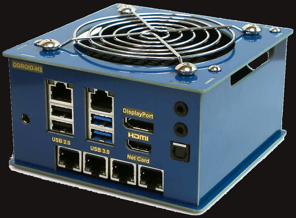
This configuration includes an addon card for a total of six 2.5Gbps Ethernet network controllers (NICs).
Network design
The six NICs on the odroid will be used like this:
- port 1: WAN - wide area network, ie. the internet. Connect this to your ISP.
- port 2: MGMT - management interface (This will be initially called
LANduring setup) - port 3: TRUNK -___ TRUNK aggregates 5Gb bandwidth from ports 3+4
- port 4: TRUNK -/
- port 5: OPT3 - available for future expansion
- port 6: OPT4 - available for future expansion
All of the home networks are defined as VLANs accessible from the TRUNK aggregate link:
- vlan 132: LAN (Home network)
- vlan 133: IOT (Internet of Things)
- vlan 134: APPS (Proxmox and Docker)
- vlan 135: WORK (Office)
Each network is in charge of a /24 address space, and a location-aware sub-domain name :
- MGMT
10.1.1.1/24- mgmt.home.example.com
- LAN
192.168.132.1/24- lan.home.example.com
- IOT
192.168.133.1/24- iot.home.example.com
- APPS
192.168.134.1/24- apps.home.example.com
- WORK
192.168.135.1/24- work.home.example.com
pfsense will act as the DNS, DHCP, and firewall services for each of these networks.
Why use VLANs?
You might be wondering, why use VLANs at all? The ODroid H3 has six physical NICs! Why not just use a separate physical port per network? Well, that totally works as long as you will only use it inside of a server rack, or if each room in your house only needs to access one network. When I bought the odroid I hadn’t planned on doing any VLANs with it at all. Name one other device at this price point that has six NICs!
The limitation though is the wiring in the home. You’re lucky if you even have wired ethernet, but how much rarer is it still to have two or more network cables going to a single room? If you want to access more than one network (wired) in a room that only has one wire coming to it, you’re going to need to implement VLANs, and managed switches in each room.
A managed network switch is required
The ODroid is just a computer with six NICs. With pfsense installed, it becomes a router, but it is not a network switch. Pfsense can expose several VLANs per port, configured as a trunk port. This just means that there is no access control over which VLANs you can access from it, all of the ones that have been configured for that port are always available to the client. This lack of control is not what you want for an environment where you might plug random untrusted devices in. You need a managed switch to connect the trunk port, and to configure the other ports to use exactly which vlans you need per port on the switch on a case-by-case basis. The switch therefore becomes an integral part of your layered security, and cannot be separated from your pfsense router.
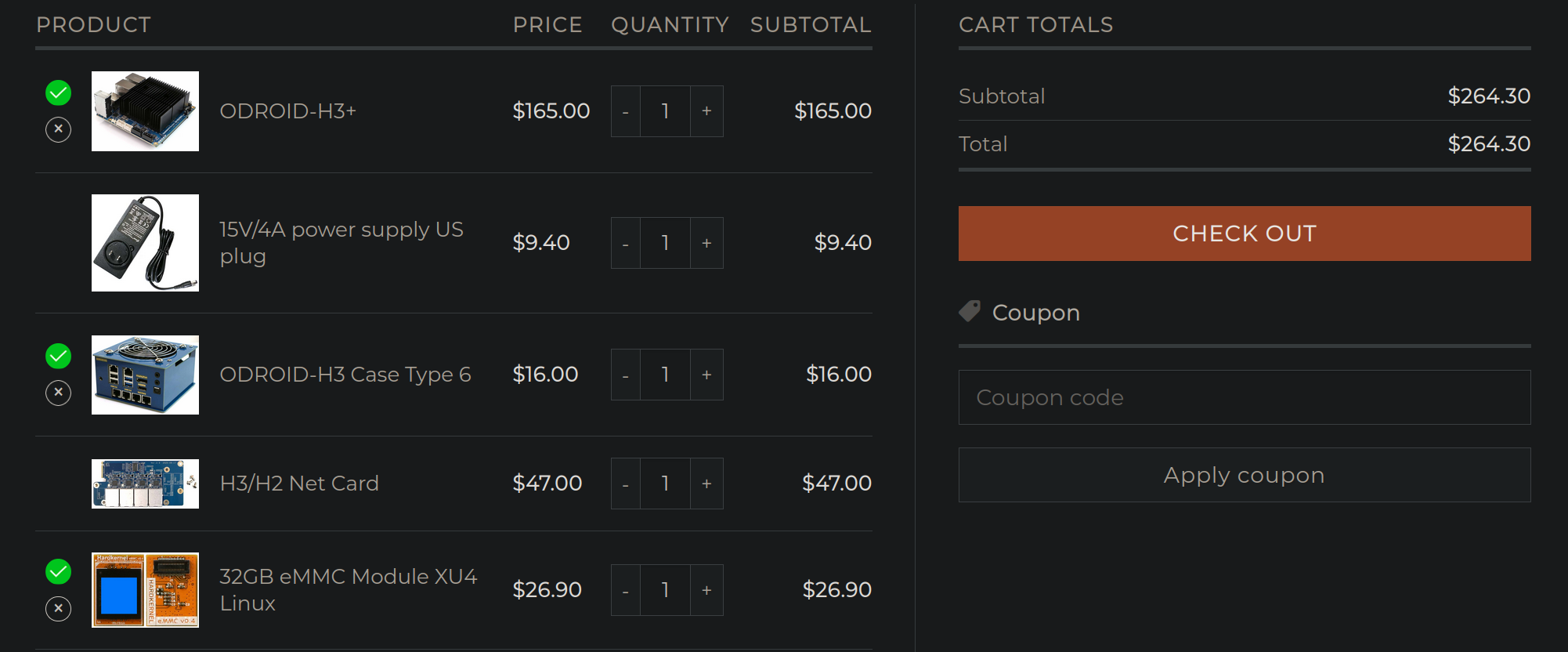
So, in addition to the H3, you will need a switch too. The one we will
be testing is the Sodola 9 Port 2.5G Smart Web Ethernet Switch, and
the same underlying hardware is also available as many vendored
variants.
Among the many favorable features of the Sodola, most notable for our application is the support for:
- Eight 2.5Gb ethernet ports
- VLAN support
- Dual-port link aggregation, for 5Gb toal bandwidth back to pfsense
VLANs will allow to host several virtual networks through the home, while going over the same copper wire. Link aggregation will allow us to combine two 2.5Gb links into one bigger 5Gb link, giving us extra speed to route things on the lan side (but the WAN is still limited by its single 2.5Gb interface).
Install pfsense
Download the .iso, dd it to a
flash drive, plug a keyboard and mouse into the router, boot it, and
install pfsense.
ODroid H3 specfic needs
The ODroid needs a specific realtek driver that is not included on the installation media. This driver can be installed from the package repository.
PFsense will boot and then immediately shutdown if it doesn’t find any network cards. That will be the case until you install the realtek driver for the card. To get it to boot and not shutdown, I temporarily plugged in a USB ethernet adapter which is supported by FreeBSD. After the network link to the internet is up, you can install the package you need.
The pkg repos that come with with PFsense 2.7.2 include the realtek
driver, so you can install it with this command:
pkg install realtek-re-kmod-198.00_3
If the version of PFsense you’re using doesn’t include the realtek
driver in their repo, you might be able to install it by pointing
pkg to the remote package file, like this:
pkg add https://pkg.freebsd.org/FreeBSD:14:amd64/latest/All/realtek-re-kmod-198.00_3.pkg
The name of this package may change as newer versions are released. Check here for updated releases
Create the boot loader config:
cat <<EOF > /boot/loader.conf.local
if_re_load="YES"
if_re_name="/boot/modules/if_re.ko"
EOF
Type exit and then choose 5) Reboot system from the menu. When the
router reboots, it should find all the interfaces.
Reset to factory defaults
In case you already have an existing pfsense system, and you want to
start from scratch, you don’t need to reinstall, you can simply reset
it to factory defaults, and then you’ll have a fresh start with which
to follow the rest of this guide. You can choose option 4) Reset to factory defaults in the console menu to do this.
Initial console setup
In the console, choose 1) Assign interfaces:
It will print out a list of all your network interfaces. In the case
of the ODroid H3 there are six interfaces named
re0,re1,re2,re3,re4, and re5.
Do VLANs need to be setup first?
This first question asks you whether to setup VLANs. For now, you
need to choose No (press n and press Enter.) as you will set it up
later using the web dashboard.
Enter the WAN interface name or 'a' for auto-detection
Enter re0 for the WAN device (this may be a different name depending
on your hardware)
Enter the LAN interface name or 'a' for auto-detection
Enter re1 for the LAN device.
Enter the Optional 1 interface name or 'a' for auto-detection
Press Enter for none, you do not need to any of the other interfaces at this time.
Set the LAN address
In the console, choose 2) Set interface(s) IP address:
It will print out a list of the interfaces you just created. Choose
2 - LAN (re1 - static).
Configure IPv4 address LAN interface via DHCP? (y/n)
The LAN interface should use a static IP address, so you should choose
n to disable the LAN interface DHCP setting (ie. pfsense should be
the LAN DHCP server, and not get its IP from any other DHCP server).
Enter the new LAN IPv4 address:
Enter the address: 10.1.1.1
Enter the new LAN IPv4 subnet bit count (1 to 32):
Enter the bit count: 24
For a WAN, enter the new LAN IPv4 upstream gateway address. For a LAN, press <ENTER> for none:
Press Enter for none (there is no upstream LAN gateway)
Configure IPv6 address LAN interface via DHCP6? (y/n)
Choose n to disable the LAN interface IPv6 DHCP setting (again,
pfesense has a static ip and will be the DHCP server)
Enter the new LAN IPv6 address. Press <ENTER> for none:
Press Enter for none (IPv6 will not be necessary for this installation.)
Do you want to enable the DHCP server on LAN (y/n)
Choose y (pfsense will be the DHCP server)
Enter the start address of the IPv4 client address range:
Enter the start address for DHCP range: 10.1.1.50
This reserves some room at the start from the 1->49 range for static ip address assignments.
Enter the end address of the IPv4 client address range:
Enter the end address for the DHCP range: 10.1.1.250
This too reserves some room at the end for static assignments.
Do you want to revert to HTTP as the webConfiguration protocol? (y/n)
Say y for now, to use unencrypted HTTP. But you may want to get a
real certificate from ACME Let’s Encrypt, and then you can turn on
HTTPS later on.
Finally the setup should conclude, and print the web configurator url,
which in the demo case is: http://10.1.1.1
You can now unplug the keyboard and monitor from the router as they won’t be needed again during normal usage.
Login to the web console
Connect a client machine into the LAN port of the router, and you
should easily acquire a IPv4 address via DHCP. Assuming you’re the
first one to connect, the address you receive should be
10.1.1.50.
On the client, open a web browser to http://10.1.1.1.
Login with the default credentials:
- username:
admin - password:
pfsense
Go through the initial setup wizard:
- Enter the hostname:
router - Enter the domain:
home.example.com - Enter the primary DNS server:
1.1.1.1(or whatever you prefer) - Enter the secondary DNS server:
1.0.0.1(or whatever you prefer) - Make sure that your browser does not automatically fill any saved
passwords into any of the fields (eg.
PPTP password), your browser does not understand the context it is in, and it likes to fill in the incorrect value here (which likely should remain empty instead). - Important set a secure admin passphrase
- Click the Check for updates button and then Finish the wizard.
Reboot the router
It is recommended to reboot after the initial config, this will help
to get the services started correctly, including the DNS resolver for
the LAN. Under Diagnostics choose Reboot and wait for the router
to reboot.
Enable the SSH server
It can be handy to be able to SSH into the router, but you need to be careful to configure it to require keys (no passwords!) and you need to keep your SSH key safe (password protected and/or use a hardware token).
Enable SSH:
- Click on
System - Click on
Advancded - Click on
Enable Secure Shell - Select from the
SSHd key onlyoption and choosePublic Key Only. - Click
Save
Add your SSH keys:
- On your workstation, copy the contents of your SSH public key file
(
~/.ssh/id_rsa.pub) or grab it from your agent (ssh-add -L). If you haven’t got a key, usessh-keygen. - Click on
System - Click on
User Manager - Click the edit button on the
adminuser. - Paste your ssh pub key into the field
Authorized SSH Keys. - Click
Save.
Rename LAN interface to MGMT
The second NIC (re1) was assigned to the LAN interface during
initial setup, which is just the default name that pfsense uses. This
NIC will actually be used only as a management interface, so let’s
rename it to MGMT:
- Click on
Interfaces - Click on
LAN - Edit the description and change it to
MGMT - Click
Save - Click
Apply Changes
Create the LAGG0 and TRUNK interfaces
(Note: These instructions do work on an older 1Gb unifi switch, but I could not get the link aggregation to work on the Sodola switch. So you may want to skip creating the LAGG device, and simply create the TRUNK interface using a single physical NIC instead.)
To increase the LAN side bandwidth, Link Aggregation can be used to
double the native link speed. The ODroid H3 has several 2.5Gbps links,
so we will take re2 and re3 and create a bonded LAGG interface
between them for an aggregate speed of 5Gbps. The network switch also
must support LACP Link Aggregation and configure the ports you connect
to be linked.
- Click
Interfaces - Click
Assignments - You should only see two interfaces:
WANandMGMT. If you see any interfaces namedOPTx(maybe you accidentally created these during the setup), you must delete them now with theDeletebutton.
Create the new aggregate link:
- Click on the
LAGGstab - Click
Addto create a new LAGG interface - Select both parent devices:
re2andre3 - Choose the LAGG protocol:
LACP - Enter the description:
VLAN LAGG - Click
Save - This will create the
LAGG0interface
Assign the interface:
- Go back to the
Interface Assignmentstab - Select the
LAGG0interface underAvailable network ports. - Click the
Addbutton next to the interface selection. - This will recreate the
OPT1interface, but assigned to theLAGG0port.
Configure and rename the interface:
- Click on
OPT1 - Click on
Enable interface - Enter the description:
TRUNK - Click
Save - Click
Apply Changes
Create the LAN VLAN
- Click
Interfaces - Click
Assignments - Click on the
VLANstab - Click
Add
Enter the new VLAN configuration:
- Parent Interface:
lagg0 - VLAN tag: 132
- VLAN priority: 0 (its the default, you can leave it empty)
- Description:
LAN - Click
Save
Click on the Interface Assignments tab
- Find the line at the bottom
Available network ports - Choose from the list:
VLAN 132 on lagg0 - opt1 (LAN) - Click on the
Addbutton on the right
This will create a new interface named OPT2. Rename the interface to
LAN now:
- Click on
OPT2. - Click on
Enable interface - Enter the description:
LAN - Enter the IPv4 Configuration Type:
Static IPv4 - Enter the IPv4 Address:
192.168.132.1 - Make sure to change the subnet size to
/24(not/32). - Click
Save - Click
Apply Changes - Notice that the Interface is automatically renamed
LAN (lagg0.132)on its configuration page to denote the physical interface(s) and the vlan id.
Turn on the DHCP server for the LAN VLAN:
- Click on
Services - Click on
DHCP Server - Click on the
LANtab - Click
Enable DHCP server on LAN interface - Enter the IP address pool range:
- Start:
192.168.132.10 - End:
192.168.132.250
- Start:
- Enter the domain name:
lan.home.example.com - Click
Save
Configure your switch
You need to read the manual for your switch to connect to the switch management interface. The manual for the Sodola 9-port switch is here
Note: I could not get link aggregation working on the Sodola switch, so the TRUNK interface is only using a single port.
The Sodola switch is configured with these ports configured from left to right:
- Port 1:
TRUNK(all tagged VLANs) - Port 2:
LAN(untagged) - Port 3:
LAN(untagged; secondary) - Port 4:
IOT(untagged) - Port 5:
APPS(untagged) - Port 6:
TRUNK2(all tagged VLANs, and goes to another switch) - Port 7: unused
- Port 8: reserved for switch management
- Port 9 (SFP+): unused
Connect a laptop to port 8, and configure the IP address:
192.168.2.2 and connect to the management interface in your browser
at 192.168.2.1. Enter the default username and password: admin /
admin
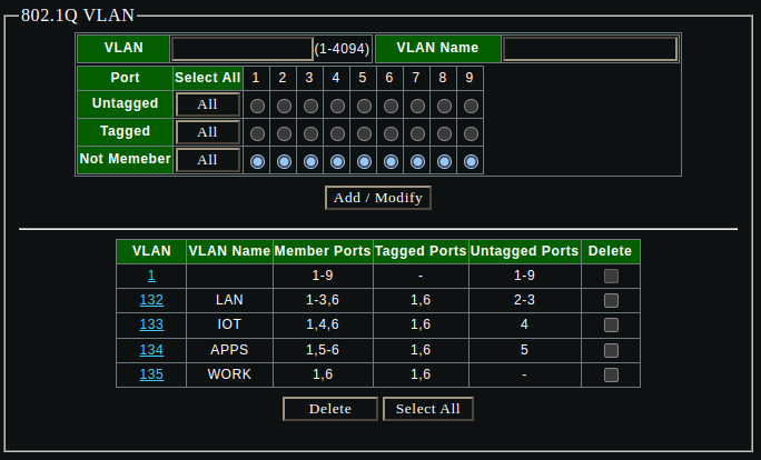
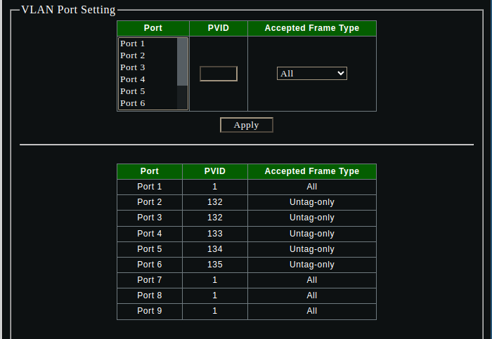
Create all the VLANs and PVID settings on the sodola switch via the management interface:
Create DNS resolver Access Lists
- Click
Services - Click
DNS Resolver - Click on the
Access Liststab - Click
Addto create a new access list - Enter the
Access List name:allow from local networks - Enter the networks:
192.168.0.0/1610.1.1.0/24
- Click
Save - Click
Apply Changes
Set the default gateway
- Click
System - Click
Routing - Select the
Default gateway IPv4:WAN_DHCP
(There’s only the one gateway, so I would have thought the setting
Automatic should have worked, but it did not. Without setting it to
WAN_DHCP the DHCP client receives no default gateway.)
Reboot pfsense
After configuring all the interfaces etc., it is important to reboot pfsense to ensure everything is reconfigured properly. I have encountered a situation several times where the config looked right, but was not actually applied, and a reboot corrected it. When in doubt, reboot.
Test the LAN
Connect a client to the port on the switch that you tagged with the
LAN (132) vlan. You should be able to get an IP address with DHCP,
and assuming you are the first client to connect, it will be
192.168.132.10.
Create the rest of the VLANs
Now repeat all of the same steps as in the Create the LAN VLAN section, but do it for the other VLANs, customizing the details for these particular networks:
IOT:- vlan tag:
133 - ipv4 address:
192.168.133.1 - DHCP range:
192.168.133.10->192.168.133.250 - DHCP domain name:
iot.home.example.com
- vlan tag:
APPS:- vlan tag:
134 - ipv4 address:
192.168.134.1 - DHCP range:
192.168.134.100->192.168.134.250 - DHCP domain name:
apps.home.example.com
- vlan tag:
WORK:- vlan tag:
135 - ipv4 address:
192.168.135.1 - DHCP range:
192.168.135.10->192.168.135.250 - DHCP domain name:
work.home.example.com
- vlan tag:
Create firewall rules per VLAN
Newly created VLANs have no firewall rules by default, and so the DENY catch-all rule applies to everything. In order to get any traffic at all going in or out of the vlan, you need to create some ALLOW rules.
Create a firewall alias for private networks
To simplify the firewall rules, create an alias to match all private networks:
- Click
Firewall - Click
Aliases - On the
IPtab, ClickAdd - Enter the name:
private_networks - Enter the description:
Private Networks - Select the type:
Network(s) - Enter the networks:
192.168.0.0/1610.0.0.0/8172.16.0.0/12- etc.
- Click
Save - Click
Apply Changes
This assumes that the pfsense WAN is not itself behind a private network, if it is, you will need to carve out any private ranges that live on the WAN side to not be included in this alias.
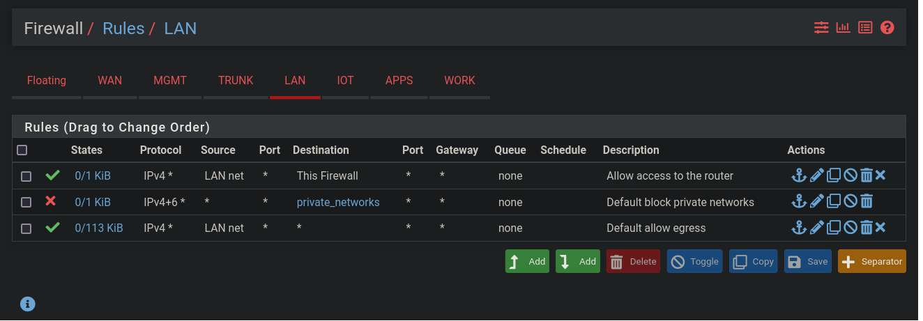
Create default firewall rules for the LAN
- Click
Firewall - Click
Rules - Click on the
LANtab - Click the
Addbutton (the one with the down arrow) to create a rule at the bottom of the list:- Select the action:
Pass - Select the interface:
LAN - Select the address family:
IPv4 - Select the protocol:
Any - Select the source:
LAN net - Select the destination:
- Choose
This firewall (self)
- Choose
- Enter the description:
Allow access to the router - Click
Save - Click
Apply Changes
- Select the action:
- Click the
Addbutton (the one with the down arrow) to create a rule at the bottom of the list:- Select the action:
Block - Select the interface:
LAN - Select the address family:
IPv4+IPv6 - Select the protocol:
Any - Select the source:
any - Select the destination:
- Choose
Single host or alias - Enter the destination alias:
private_networks(this should auto-complete, using the alias you created above)
- Choose
- Enter the description:
Default block private networks - Click
Save - Click
Apply Changes
- Select the action:
- Click the
Addbutton (the one with the down arrow) to create a rule at the bottom of the list:- Select the action:
Pass - Select the interface:
LAN - Select the protocol:
Any - Select the source:
LAN net - Enter the description:
Default allow egress - Click
Save - Click
Apply Changes
- Select the action:
You can copy these default rule to each of the other VLANs:
- Select all of the new rules by clicking on the checkboxes.
- Click the
Copybutton. - Select the destination interface: (do this once for
IOT,APPS, andWORK) - Click
Enable Interface Address/Net conversion. - Click
Paste
You can now add any other custom rules per network that you need,
these should go above the default rules, and below the Allow access to the router rule.
You can discuss this blog on Matrix (Element): #blog-rymcg-tech:enigmacurry.com
This blog is copyright EnigmaCurry and dual-licensed CC-BY-SA and MIT. The source is on github: enigmacurry/blog.rymcg.tech and PRs are welcome. ❤️